|
|
|
|
Installing on-board socket (Repair Manuals 6th edition Part number 01059 7 721 683) |
|
|
BMW R 1200 GS Adventure (0380) |
|
|
||||||||||
| Preparatory work |
|
Removing front and rear seats |
|
Removing left side cover |
|
Removing left side panel |
|
Remove the right side cover |
|
Removing right side panel |
|
Removing right trim panel of fuel tank |
|
Removing intake air pipe |
|
Removing slipstream deflector, left |
| Core activity |
|
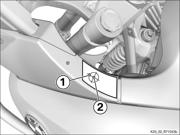
(+) Affixing drilling template for on-board socket
(-) Affixing drilling template for on-board socket
|
|
|
|
|
(+) Drilling pilot hole in font-wheel cover for on-board socket
(-) Drilling pilot hole in font-wheel cover for on-board socket
|
|
|
|
||||||||||||||||||||||||||||||||||||
|
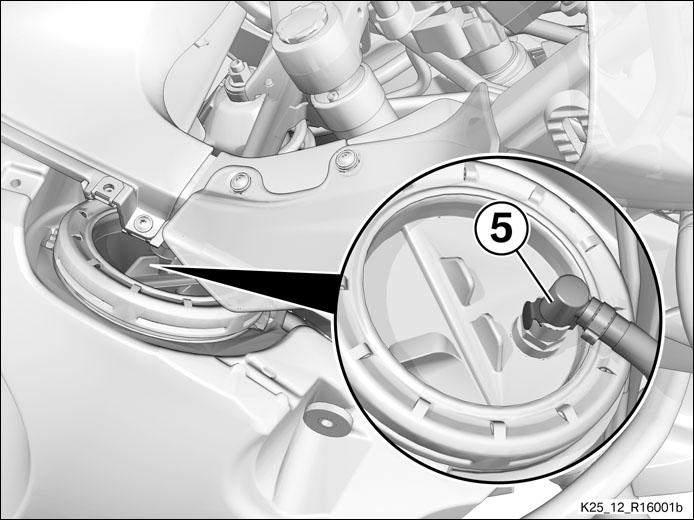
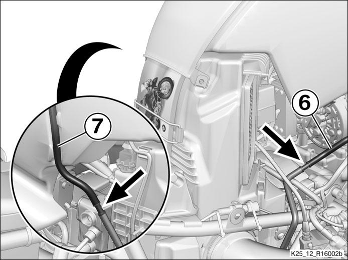
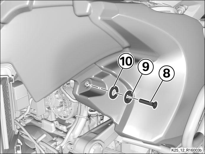
(+) Removing fuel tank
(-) Removing fuel tank
|
|
|
|
|
|
|
||||||||||||||
|
|
|
|
|
|
|
|
|
|
|
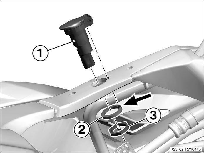
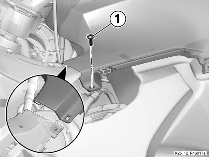
(+) Installing on-board socket in front-wheel cover
(-) Installing on-board socket in front-wheel cover
|
|
|
|
|
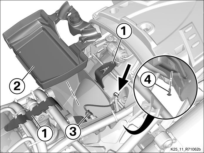
(+) Removing tool compartment and preparing for wiring
(-) Removing tool compartment and preparing for wiring
|
|
|
|
|
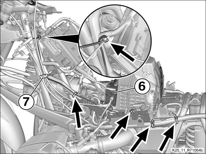
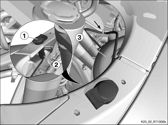
(+) Routing cable for on-board socket
(-) Routing cable for on-board socket
|
|
|
|
|
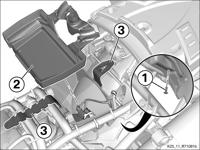
(+) Installing tool compartment
(-) Installing tool compartment
|
|
(+) Installing fuel tank
(-) Installing fuel tank
|
|
|
|
|
|
|
|
|
|
|
||||||||||||
|
|
|
|||||||||||||||||||||||||||||
|
|
|
|
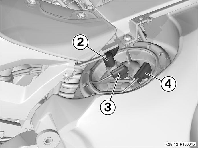
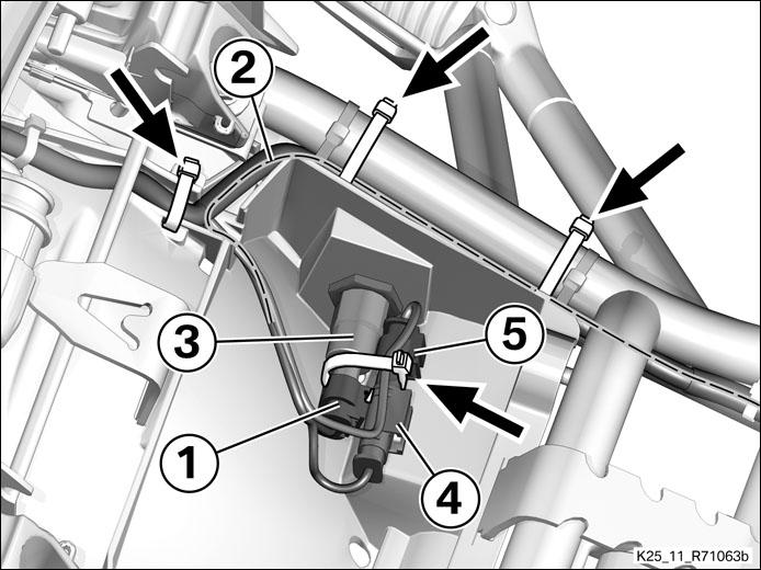
(+) Connecting on-board socket
(-) Connecting on-board socket
|
|
|
|
|
(+) Function check and fuse protection
(-) Function check and fuse protection
|
|
|
||||||
|
||||||||||
|
| Finishing work |
|
Installing left slipstream deflector |
|
Installing intake air pipe |
|
Install the right trim panel of fuel tank |
|
Installing right side panel |
|
Installing right side cover |
|
Installing left side panel |
|
Installing left side cover |
|
Installing front and rear seats |
|
Final check of work performed |

 Technical data
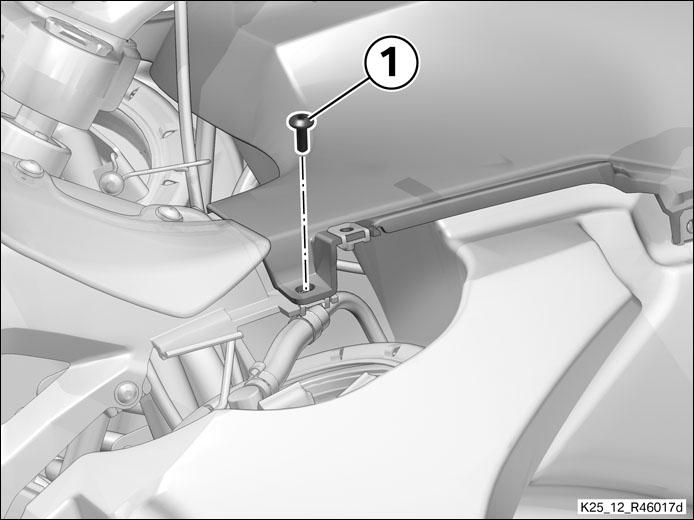

 Tightening torques
 Fluids and lubricants
