 |
|
|
|
|
Replacing ESA spring strut, front, for conversion
Electronic Suspension Adjustment (ESA) |
|
|
|
|
|
|
| Preparatory work |
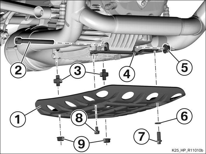
| Removing engine guard |
|
|
| Installing engine lifter | ||||||

|
|
|
Removing front and rear seats |
|
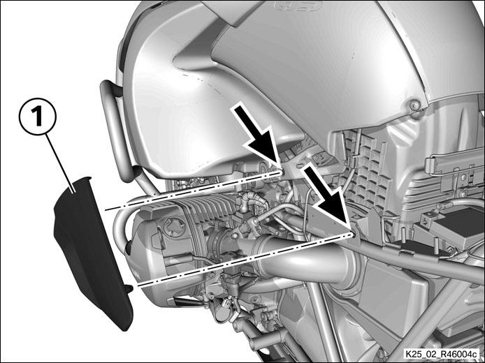
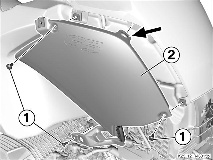
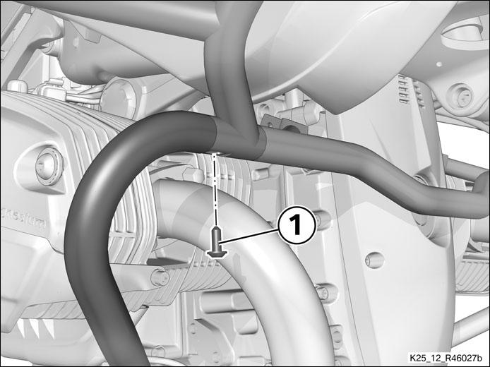
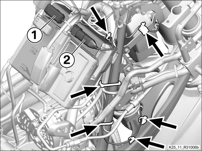
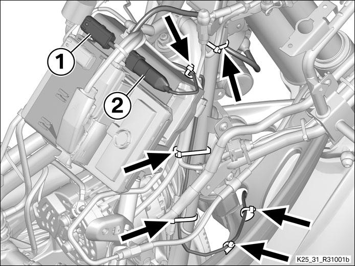
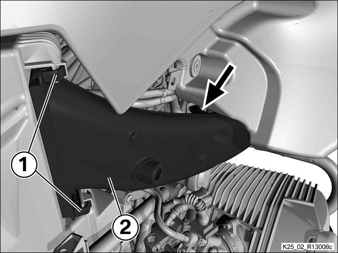
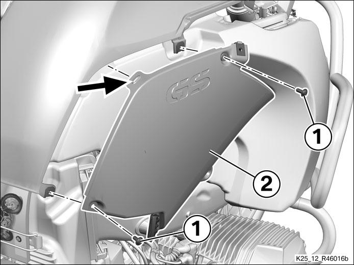
Unclip side cover (1) from the holders (arrows) and remove. |
|
Remove the right side cover |
|
|
|
|
|
|
|
|
||||||
|
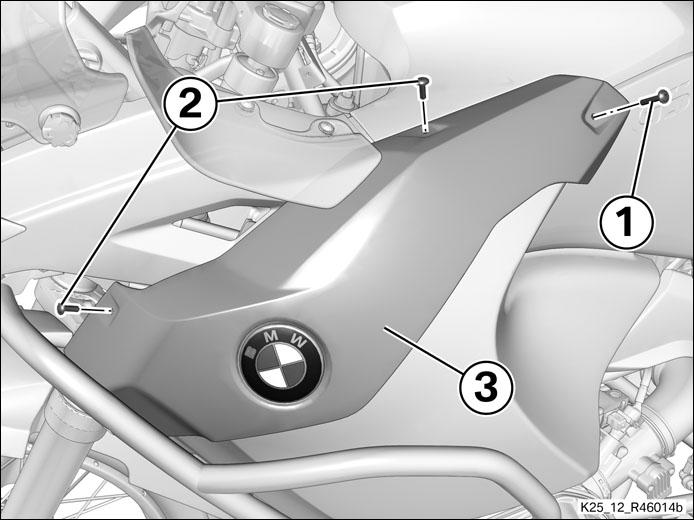
Removing left trim panel of fuel tank |
||||||
|
|
|
|
|
|
Remove screws (1) on left and right.
|
|
|
||||||||||||||
|
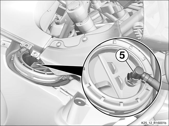
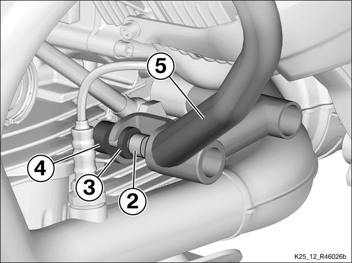
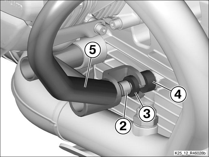
Disconnect fuel return line (5).
|
||||||||||||||
|
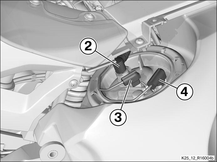
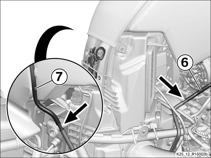
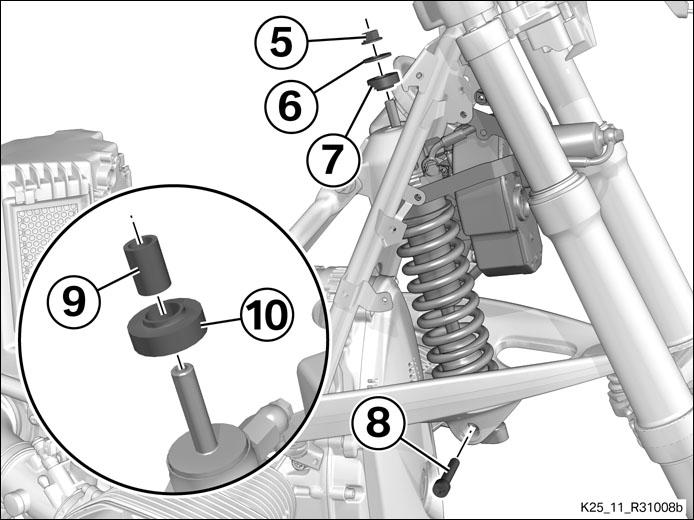
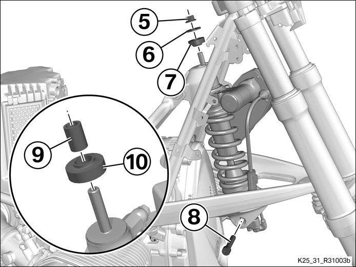
Disconnect breather hose (6) and overflow hose (7) at the connectors (arrows).
|
|
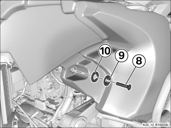
Remove screws (8) with washers (9) and rubber washers (10) on left and right.
Lift the fuel tank up and to the rear to remove.
|
|
|
|
|
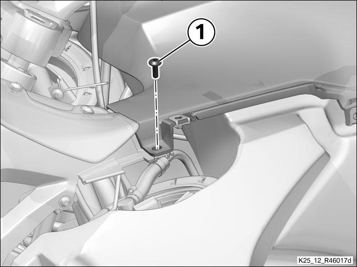
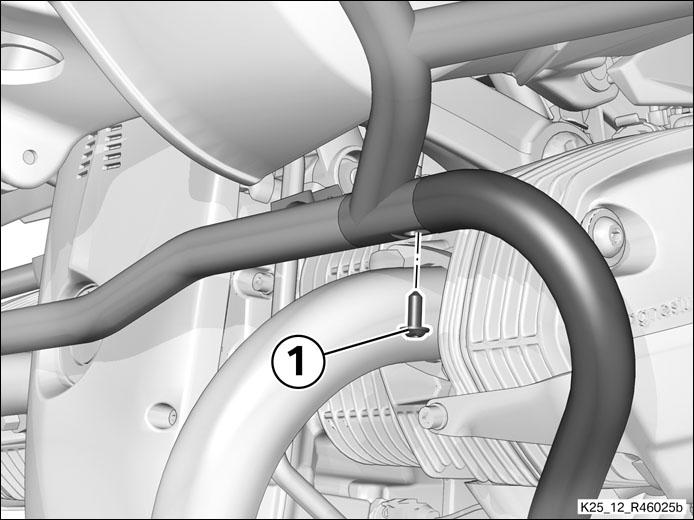
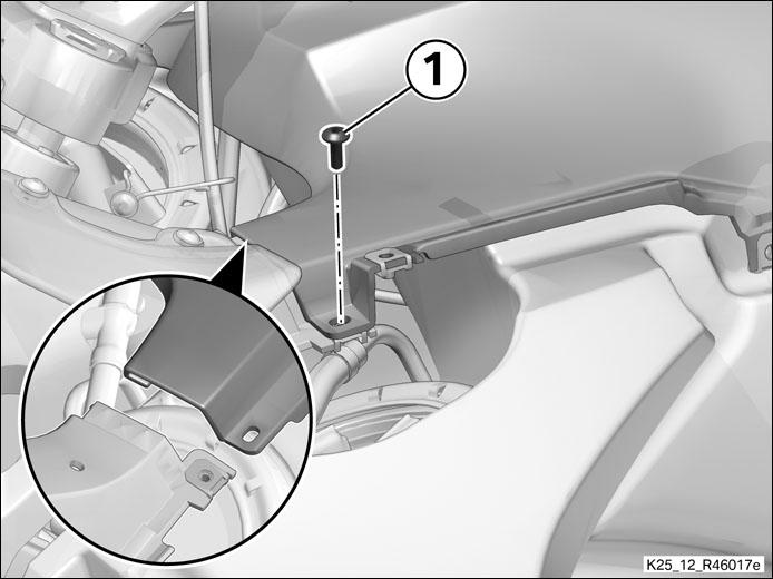
Remove screw (1).
|
|
|
|||||
|
|
||||||
|
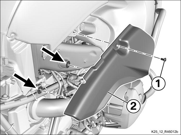
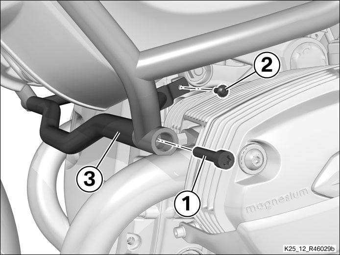
Remove screw (1). |
|||||
|
|
|||||
|
|
|
|
|||||
|
|
||||||
|
Removing belt guard |
||||||
|
|
|||||
|
|
| Core activity | |
|
|
|
|
Removing front spring strut (manufacturer SHOWA) Part no 31427702732 |
|
|
|
|
||||||||||||||||||||||||||||||||||||
|
|
|||||||||||||||||||||||||||||||||||||
|
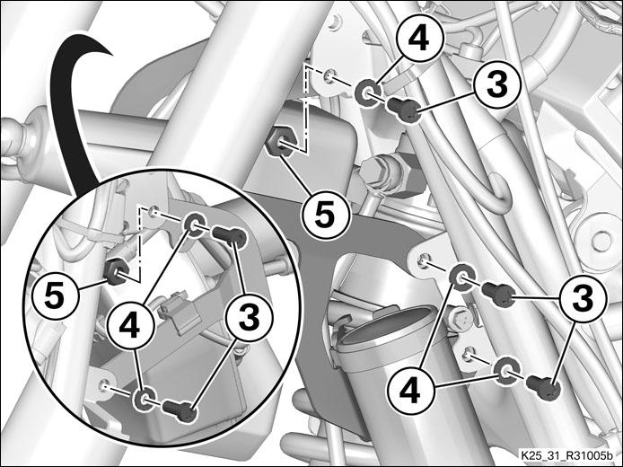
Remove screws (3) with washers (4) and at top with nuts (5). |
||||||||||||||||||||||||||||||||||||
|
|
|||||||||||||||||||||||||||||||||||||
|
|
||||||||||||||||||||||||||||||||||||
|
|
|||||||||||||||||||||||||||||||||||||
|
Install the front spring strut (manufacturer WP Suspension) Part no 31427728210 about 1.452,00 EUR |
|||||||||||||||||||||||||||||||||||||
|
|
|||||||||||||||||||||||||||||||||||||
|
|
||||||||||||||||||||||||||||||||||||
|
|
|||||||||||||||||||||||||||||||||||||
|
|
||||||||||||||||||||||||||||||||||||
|
|
|||||||||||||||||||||||||||||||||||||
|
|
||||||||||||||||||||||||||||||||||||
|
|
|||||||||||||||||||||||||||||||||||||
|
|
||||||||||||||||||||||||||||||||||||
|
|
|||||||||||||||||||||||||||||||||||||
| Finishing work | |||||||||||||||||||||||||||||||||||||
|
|
|||||||||||||||||
|
Installing belt guard |
|||||||||||||||||
|
|
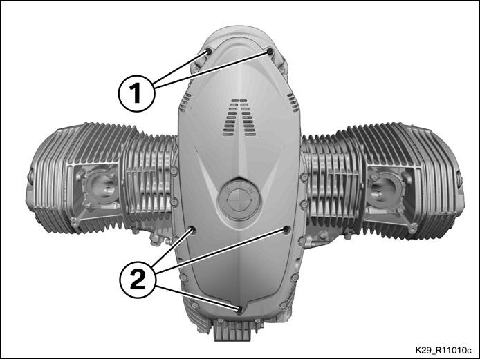
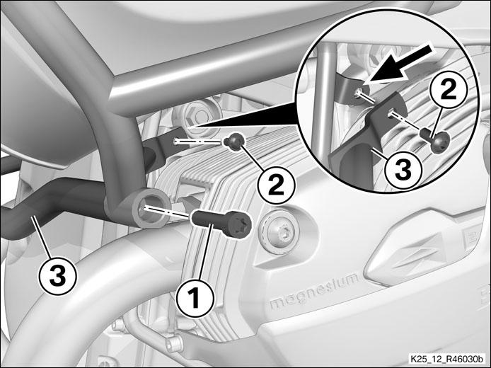
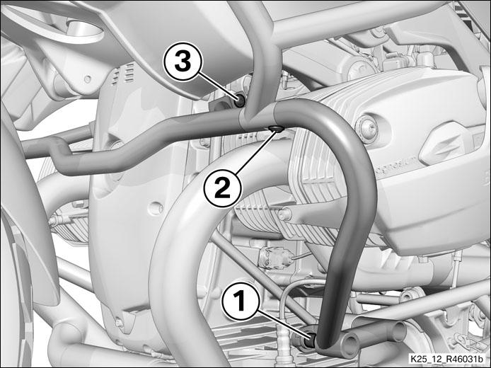
Install the belt guard with screws (1) and (2).
|
||||||||||||||||
|
|
|||||||||||||||||
|
Installing centre section of crash bar |
|||||||||||||||||
|
|
||||||||||||||||
|
|
|||||||||||||||||
|
Installing side section, left crash bar |
|||||||||
|
|
|
||||||||
|
|
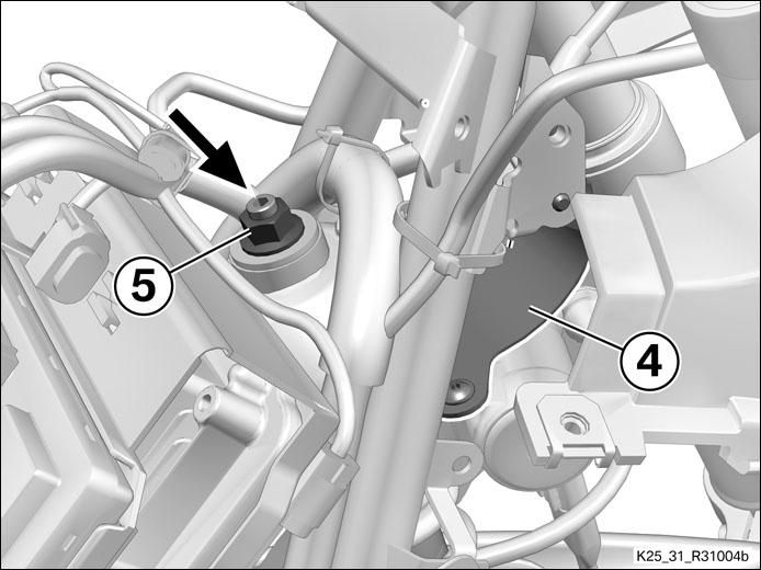
Loosely install screw (1).
|
||||||||
|
|
|
Installing side section, right crash bar |
|||||||||
|
|
|
||||||||
|
|
Loosely install screw (1).
|
|
Secure the crash bar |
|||||||||||||||||||||||||||||||||||
|
|
||||||||||||||||||||||||||||||||||
|
|
|||||||||||||||||||||||||||||||||||
|
Installing fuel tank |
|||||||||||||||||||||||||||||
|
|
Push the fuel tank from behind into the rubber mounts on the frame. Make sure that no lines, hoses or Bowden cables are trapped. Connect breather hose (6) and overflow hose (7) at the connectors (arrows).
|
||||||||||||||||||||||||||||
|
|
|||||||||||||||||||||||||||||
|
|
||||||||||||||||||||||||||||
|
|
|||||||||||||||||||||||||||||
|
|
|
||||||||||||||||||||||||||||
|
|
|||||||||||||||||||||||||||||
|
|
|
||||||||||||||||||||||||||||
|
|
|||||||||||||||||||||||||||||
|
|
Connect fuel return line (5).
|
||||||||||||||||||||||||||||
|
|
||||||
|
Installing intake air pipe |
||||||
|
|
|
|
|
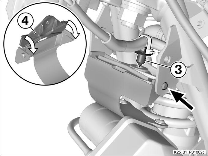
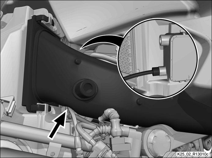
Check that the throttle-valve cable is seated in the guide of the air intake pipe (arrow) and that it is has not been pulled out of the divider (detail).
|
|||||
|
|
|
|||||
 |
|
|||||
|
|
|
Installing right side cover |
|
|
|
||||||||
|
Installing left side panel |
|
|
Hold side cover (1) in position and push the snap-fit studs into the holders (arrows). |
|
|
|
|
|
||||||||||||||
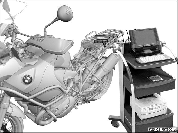
| Connecting BMW Motorrad diagnostic system to motorcycle | |||||||||||||||
|
|
|||||||||||||||
|
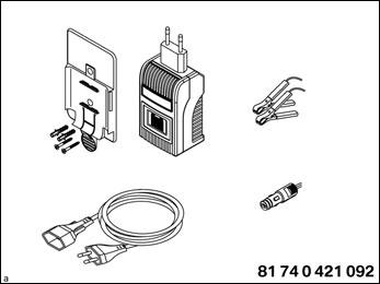
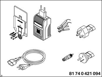
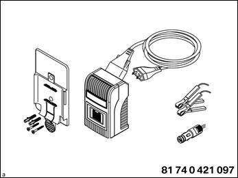
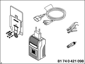
Workshop equipment BMW Motorrad battery charger (version for Europe without GB) BMW Motorrad battery charger (GB/AUS/NZL version) BMW Motorrad battery charger (Japan version) BMW Motorrad battery charger (USA/CAN version)
|
||||||||||||||
|
|
|||||||||||||||
|
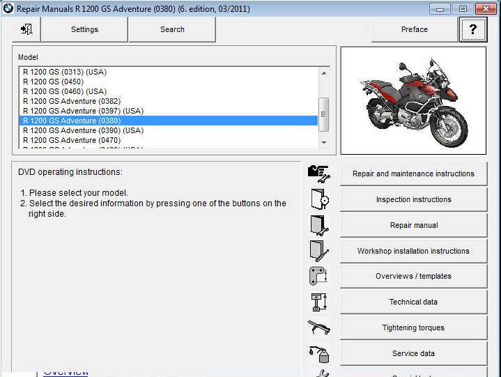
Retrofit with CIP (Coding, Individualisation and Programming) or ISTA P |
|||||||||||||||
|
Precondition Engine is off. Battery is fully charged and battery charger is connected. Note Do not attempt to perform work of any other kind on the motorcycle while programming/coding is in progress.
Switch off all electrical consumers. Begin by switching on the BMW Motorrad diagnostic system and wait for it to power up. From this point on, follow the instructions issued by the diagnostic system. Perform diagnosis. Rectify faults, if found, before starting programming/coding. Start programming/coding with the CIP program and follow the instructions issued by the diagnostic system. Select the retrofit just completed from the range offered in CIP and step through the rest of the procedure.
|
|||||||||||||||
|
|
|||||||||||||||
|
Disconnecting BMW Motorrad diagnostic system from motorcycle |
|||||||||||||||
|
Terminate the diagnosis session correctly and switch off the ignition. Disconnect KOMET from the motorcycle and screw the cap onto the diagnosis plug. Disconnect the BMW Motorrad battery charger from the motorcycle.
|
|
|
|
|
| Installing front and rear seats | |
|
|
| Removing engine lifter | ||||||||||||
|
|
|
|||||||||||
|
Installing engine guard |
|
|
|
|||||||||||||||||||||||||||||||||||||
| Final check of work performed | ||||||||||||||||||||||||||||||||||||||
|
Check that - the work as performed achieved the intended purpose. - all reservoirs and containers have been filled and that all fluids and lubricants are at their correct levels. - all threaded fasteners released beforehand have been correctly retightened. - the fuel system is free of leaks. - the lights and signalling equipment are fully operational and that the motorcycle is roadworthy. - the brake pads of the front and rear brakes are bedded against the brake discs.
|
||||||||||||||||||||||||||||||||||||||
| Repair Manuals R 1200 GS Adventure (0380) (6. edition, 03/2011) |